NORTHEAST CONTROLS INCORPORATED
INSTALLATION • OPERATION • MAINTENANCE INSTRUCTIONS
Models WD2010L • WD2010 • WD2010H Washdown Stations
Telephone: 1-201-419-6111
Fax: 1-201-419-6109
Website: www.nciweb.com
Email: sales@nciweb.com
Installation: 1004 Rev 3
Issued: March 2026
Table of Contents
- Introduction
1.1 Features and Specifications
1.2 Design Ratings
1.3 Recommended Operating Ranges - Inspection and Performance Confirmation
2.1 Receiving Inspection
2.2 User’s Rating Inspection - Installation
3.1 Mounting
3.2 Piping and Precautions - Operation
4.1 Pre-Operational Check
4.2 Normal Operation
4.3 Shutdown - Maintenance
5.1 Preventive Maintenance Schedule
5.2 Maintenance Procedures
5.3 Troubleshooting
5.4 Removal, Disassembly & Reassembly - Parts List and Exploded View
DANGER
Always wear safety glasses, face shield, wet suit, boots, and gloves when installing, servicing, or operating a washdown station.
Failure to follow these instructions may result in serious personal injury or property damage. Read and understand this entire manual before beginning any work.
1. Introduction
1.1 Features and Specifications
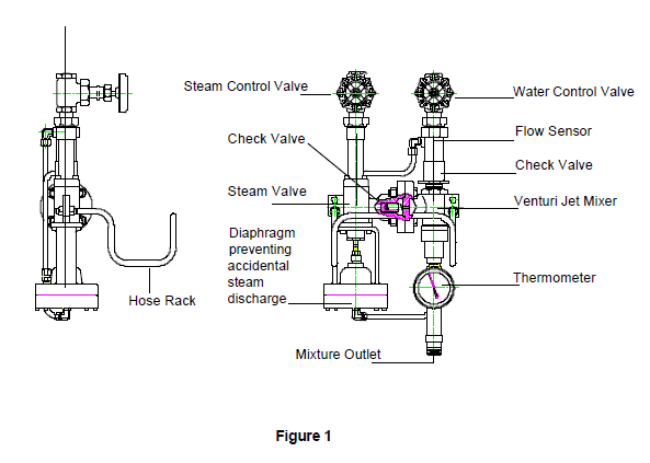
The Northeast Controls Washdown Station is a complete, pre-engineered package designed for efficient hot-water cleanup in industrial environments. It heats water by direct steam injection and includes:
- Manually operated steam and water supply valves
- Diaphragm-operated steam valve (opens at 5–6 GPM; 3–4 GPM for WD2010L)
- Flow-sensing orifice
- Integral steam and water check valves
- Positive steam safety shut-off
- Discharge temperature gauge
- Integral direct steam injection heater
- Swivel hose fitting
- Wall-mounting system
- Stainless-steel hose rack
- Optional 25 ft or 50 ft hose with trigger spray gun or automatic shut-off lance
Important Note
Northeast Controls cannot guarantee suitability for every application. The end user is responsible for verifying compatibility with their specific conditions.
1.2 Design Ratings
To determine maximum allowable working pressure at your operating temperature, refer to Northeast Controls dimension sheets or the specific limits stated on your Northeast Controls product proposal.
1.3 Recommended Operating Ranges
| Model | Saturated Steam Pressure (psig) | Water Pressure (psig) | Discharge Flow Range |
|---|---|---|---|
| WD2010L | 10 – 60 | 30 – 80 | 3 – 4.5 GPM |
| WD2010 | 35 – 150 | 30 – 80 | 3 – 8.5 GPM |
| WD2010H | 60 – 200 | 30 – 80 | 3 – 9 GPM |
Best Performance Tip: Supply water at 5–10 psi below steam pressure.
Maximum Discharge Temperature: 190 °F (do not exceed).
DANGER
Never exceed the design ratings or operating ranges shown above. Operation without the hose and approved nozzle can cause serious injury or damage.
2. Inspection and Performance Confirmation
2.1 Receiving Inspection
- Inspect all components for shipping damage immediately upon receipt.
- If damage is found, do not install. Notify the carrier and request an inspection.
2.2 User’s Rating Inspection
Confirm the following before installation:
- Unit matches your purchase order.
- Site conditions match the purchase order.
- Operating conditions are within the ranges in Section 1.3.
- Materials are compatible with your fluids and environment.
Important
If any item above does not match, stop and contact Northeast Controls for guidance.
3. Installation
Use only qualified technicians familiar with this equipment and this manual.
Reference Drawings
Use your Northeast Controls dimension sheets or product proposal for exact dimensions. See Figure 1 for connection locations.
3.1 Mounting
- Recommended orientation: steam and water inlets vertical (thermometer upright, discharge pointing down).
- Remove manual valves by loosening the union nuts.
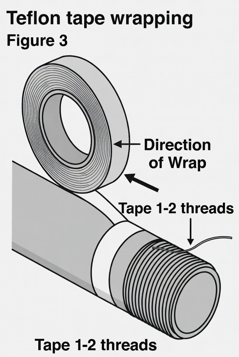
- Install valves on inlet piping using Teflon tape (or equivalent) on male threads.
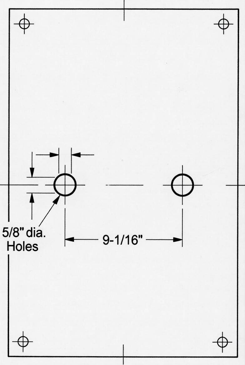
- Drill two 5/8 in. holes (9-1/16 in. apart, horizontal) in the wall. Insert bolt anchors.
- Mount unit using 3/8 in. bolts and pipe spacers.
- Re-tighten unions after mounting.
3.2 Piping and Precautions
- Use piping with minimal flow resistance.
- Install pressure gauges near inlets (recommended).
- Steam must have ≤ 20 °F superheat.
- Keep steam line short, clean, insulated, and trapped.
- Do not pipe-load the unit—support by wall bracket only.
- Install steam strainer/trap and water strainer.
DANGER
The washdown station is a complete system. Operating without hose and nozzle will cause uncontrolled discharge and possible injury.
4. Operation
4.1 Pre-Operational Check
- Verify all installation steps are complete.
- Close both manual valves.
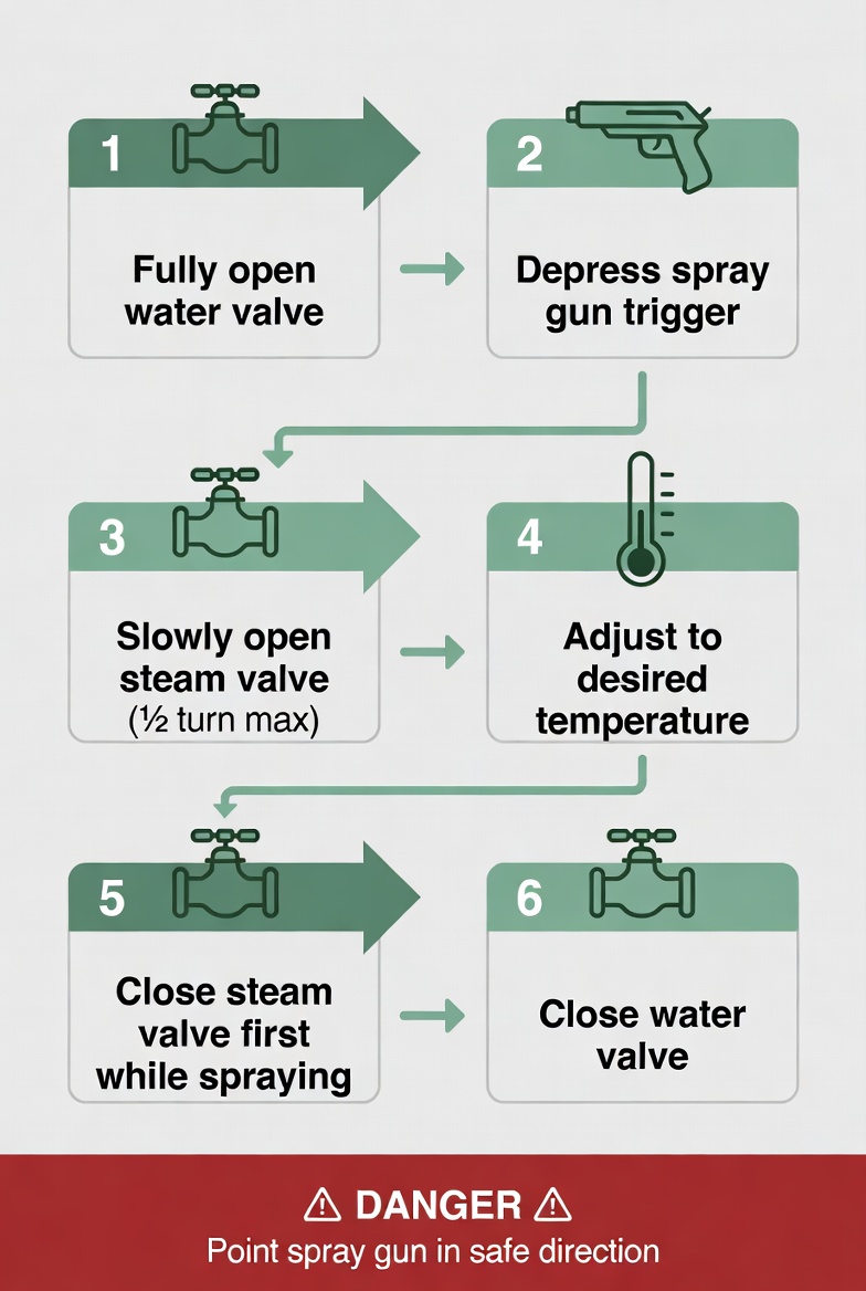
4.2 Normal Operation
- Open the water valve fully (leave open during use).
- Depress spray-gun trigger for full water flow.
- Slowly open the steam valve (max ½ turn) while spraying.
- Adjust steam valve until desired temperature is reached.
Important
Always point the spray gun in a safe direction when adjusting temperature.
4.3 Shutdown
- While squeezing the trigger, close the steam valve first (allows unit to cool).
- Release trigger, then close the water valve.
DANGER
Do not perform maintenance until the unit is depressurized, cooled to ambient temperature, and drained.
5. Maintenance
5.1 Preventive Maintenance Schedule
Develop a schedule based on your application. Regularly inspect:
- Corrosion and debris on all components
- Tightness of connections
- Outlet temperature setting
- Steam strainer and trap
- Hose and spray gun for wear
- Mounting bolts
5.2 Maintenance Procedures
- Threaded leaks: remake with Teflon tape.
- O-ring/gasket leaks: tighten or replace (never reuse deformed seals).
- Diaphragm leaks: tighten cap or replace diaphragm.
- Stem packing: tighten gland ⅛ turn at a time; replace if needed.
- Internal leaks: replace stem or seat; contact Northeast Controls if unresolved.
5.3 Troubleshooting
| Problem | Possible Cause | Recommended Action |
|---|---|---|
| Diaphragm steam valve fails to open | Water flow < 5–6 GPM (3–4 GPM for L model) Blockage in unit or piping Damaged diaphragm | Increase water pressure/flow Flush unit and lines Disassemble and replace diaphragm |
| Outlet temperature slow to respond | Condensate in steam line | Install/correct steam trap |
| Outlet temperature too low | Operating conditions out of range Water pressure too high vs. steam | Verify conditions with Northeast Controls Install water pressure regulator (5–10 psi below steam) |
| Bursts of steam in spray | Excessive steam flow / temperature > 190 °F | Reduce steam or increase water flow |
5.4 Removal, Disassembly & Reassembly
DANGER
Depressurize, cool, and drain the unit completely before any disassembly.
Preparation
Work on a clean bench with a vise. Refer to Figure 5 for part numbers.
Follow the detailed water-section and steam-section steps exactly as shown in the original manual (Sections 3.1 and 3.2 of the disassembly procedure). Discard all O-rings and Teflon packing—never reuse.
Reassembly
Follow the reverse sequence with new seals. Torque values:
- Diaphragm cap screws: 3–4 ft-lbs
- Extension cap screws: 7–8 ft-lbs
After reassembly, remount and test per Sections 3 and 4.
6. Parts List & Exploded View
(See attached Table and Figure 5 for complete reference numbers and descriptions.)
Figure 5 – WD2010 Washdown Station Exploded View
(Original exploded diagram retained for accuracy; all part numbers unchanged.)
Quick Reference Operating Summary (laminate and post near unit)
- Open water valve fully
- Depress trigger
- Slowly open steam valve
- Adjust for desired temperature
- Close steam first, then water
Contact Northeast Controls
For parts, service, or technical support: 1-201-419-6111 or sales@nciweb.com
For a printed PDF version contact Northeast Controls.