IMPORTANT SAFETY WARNINGS
- DO NOT use with steam service.
- DO NOT point the spray nozzle at any person or any part of the body. High-temperature liquids under pressure can cause serious burns or injury.
- DO NOT exceed 200°F (93°C) temperature.
- DO NOT exceed 200 psi pressure.
- DO NOT drop the nozzle on the trigger, as this may cause accidental activation and spray hot liquid onto personnel.
Introduction
The Model FT18 Spray Nozzle is a heavy-duty, impact-resistant spray nozzle featuring a stainless steel body and a replaceable synthetic rubber cover. It delivers a variable liquid spray pattern—from a hollow cone to a straight stream—controlled by the trigger. The light trigger pull allows precise control of the spray pattern. The heat-resistant rubber cover keeps the handle comfortable even with hot liquids. The inlet connection is 1/2″ NPT and is compatible with 3/4″ garden hose thread (female) swivel connectors, as well as 5/8″ or 3/4″ hose shank connections.
Features
- Maximum pressure and temperature rating: 200 psi at 200°F
- Single-piece stainless steel body
- Stainless steel valve stem
- Viton valve seat and Buna O-ring seals
- Comfortable hand grip
- Easy operation designed to reduce operator fatigue
- Replaceable rubber body cover provides thermal insulation and protects against wear
- All components are user-serviceable for easy repair
Installation
- Ensure the water supply valve is turned off.
- Attach the FT18 Spray Nozzle to a hose rated for the anticipated maximum pressure and temperature.
- Verify that all connections are the correct type, secure, and leak-proof.
- Hold the nozzle in a downward vertical position with the arrows on the body pointing away from you, then slowly open the water supply valve.
- After confirming all safety precautions are in place, begin spraying by gently squeezing the trigger.
Additional Warnings and Safety Precautions
IMPORTANT: Read all instructions before using the spray nozzle.
- For water use only.
- Always point the nozzle in the direction of the arrow shown on the side of the nozzle before spraying.
- If equipped with a trigger lock ring, release it before completing the spraying operation.
- Operator and nearby personnel should always wear proper clothing and eye protection.
Maintenance
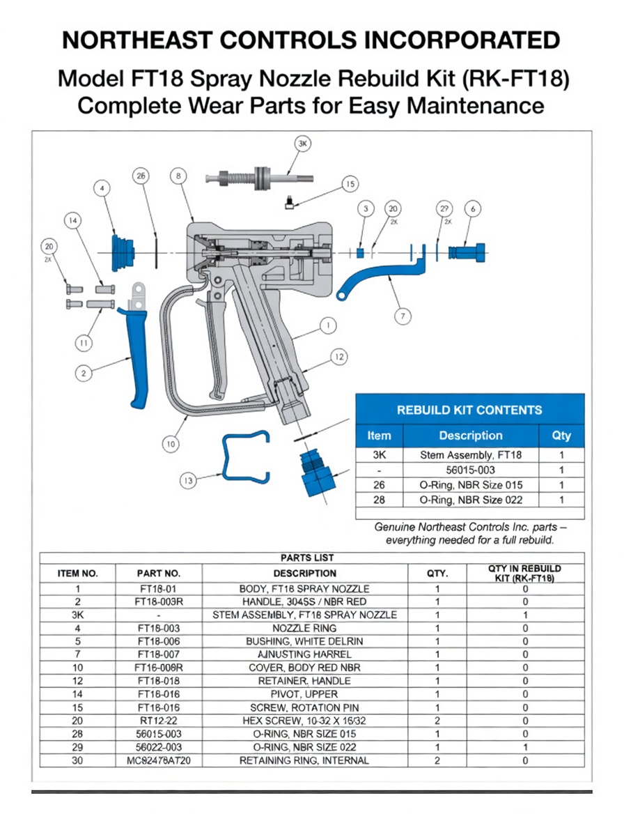
With proper care, your Model FT18 Spray Nozzle will provide years of reliable service. Inspect parts regularly and replace them as needed with genuine Northeast Controls Inc. parts.
Disassembly Procedure
If disassembly is required, follow these steps:
- Turn off the water supply valve. Release all pressure and liquid from the hose by operating the trigger until flow stops.
- Disconnect the FT18 Spray Nozzle from the supply connection.
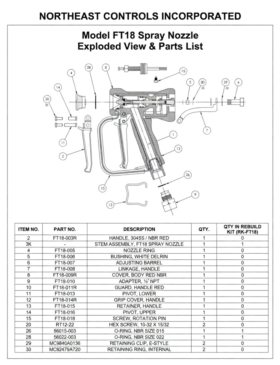
- Remove the COVER (8) by pushing up firmly on the front end until it clears the BODY (1), then slide it back and off.
- Remove the NOZZLE RING (4) using a 1-1/4″ wrench, turning counter-clockwise. Remove O-RING (28) from the GUARD (10) and replace if damaged.
- Loosen the ADAPTER (9) by partially unscrewing it from the BODY (1). Reposition or remove the GUARD (10) as needed.
- From the rear, remove RETAINING RING (30) and unscrew the BARREL (5) counter-clockwise.
- Remove the front RETAINING RING (29) and slide off the LINKAGE SLEEVE (15). Be careful not to lose the stem key (part of STEM (3K)).
- Gently pull the STEM (3K) and spring out from the front.
- Push the cartridge assembly forward through the rear stem opening in the BODY (1) using a narrow rod. Avoid damaging the BUSHING (5). (If the bushing is damaged, a replacement is available from Northeast Controls Inc.)
- If needed, remove the LINKAGE (7) by taking out SCREW (20) and POST (11).
- The GRIP (12) can be slid down and removed from the BODY (1) if necessary.
Assembly Procedure
Before reassembly, apply a moisture-resistant valve lubricant such as Dow Corning MOLYKOTE 111 to all O-rings and seals.
Apply LOCTITE 243 to SCREWS (20) when assembling with POST (11) and POST (14). Use an appropriate anti-seize compound on other threaded connections.
- Ensure the BODY (1) is clean and undamaged, with smooth interior seal surfaces.
- Apply lubricant to the outer cartridge O-rings of the STEM ASSEMBLY (3K).
- Verify the BUSHING (5) is properly installed. If replaced, it must be reamed to 0.249″/0.250″ after pressing in.
- Insert the STEM ASSEMBLY (3K) into the BODY (1) and push firmly until fully seated.
- Insert the NOZZLE RING (4) through the corresponding hole in the GUARD (10).
- Install O-RING (28) onto the NOZZLE RING (4) and lubricate it.
- Compress the spring and screw the NOZZLE RING (4) into the BODY (1). Hand tighten initially.
- Install O-RING (26) onto the ADAPTER (9), pass it through the GUARD (10), align the GUARD with the body, and tighten securely.
- Fully tighten the NOZZLE RING (4).
- From the rear, insert the stem key into the STEM, slide on the LINKAGE SLEEVE (15), and secure with two RETAINING RINGS (29).
- Screw on the BARREL (5) and secure with RETAINING RING (30).
- Install the RUBBER COVER (8) by sliding it over the rear of the BODY (1), then pushing it forward and down firmly.
- Test the reassembled nozzle for leaks and proper operation.
Please contact Northeast Controls Inc. if you require assistance.